Hollow Pin Chains for Warehouse Automation
Warehouse and intralogistics equipment needs repeatable motion, accessible service and robust fixtures for totes, cartons and transfer devices. Hollow pin chains can provide attachment points without permanently welding every carrier to the chain.
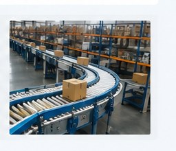
Application design checklist
Typical uses
Tote transfer devices, lift/transfer modules, carton handling, accumulation fixtures and special carrier conveyors can use hollow pins for removable hardware.
Automation interface
The chain should be considered together with sensors, stops, servo indexing, guides and guarding. Mechanical repeatability depends on the full conveyor path, not only the chain pitch.
Serviceability
Design pins, rods and retainers so maintenance teams can change a damaged fixture without disturbing a long conveyor section. Keep replacement dimensions controlled.
RFQ data
Include throughput, start/stop frequency, product mass, conveyor length, center distance, sprocket tooth counts, lubrication regime and required attachment spacing.
How to specify the chain and attachment together
Start with the conveyor layout and sprocket centers. Record the exact pitch, roller or bush diameter, inside width, plate height and hollow-pin bore. Then define the component that passes through the pin: its diameter, material, unsupported span, retention method and whether it rotates or remains fixed. If two chains are connected by the same rod, note the strand spacing and how sprocket timing is maintained.
Operating conditions complete the specification. Include steady load, peak or shock load, speed, starts per hour, temperature, corrosion or cleaning exposure, lubrication restrictions and expected maintenance interval. For existing machinery, photographs of the chain path, guides, sprockets and attachments are often as useful as a model number.
Frequently asked questions
Can I select by pitch alone?
No. Pitch is only one dimension. Hollow-pin bore, roller/bush geometry, inside width, plate height and sprocket form must also match the machine.
Can a cross-rod connect two parallel chains?
Yes, that is a common reason to use hollow pins, but the design must maintain sprocket timing and guide parallelism so the rod does not force the strands out of alignment.
Should I send an attachment drawing?
Yes. A dimensioned drawing or clear sample photo helps confirm rod diameter, retention, spacing and interference with the chain plates or guides.
Why hollow pins are useful in this application
Hollow pin chain gives the machine designer a repeatable mechanical interface along the chain. Rods, bolts and fixtures can pass through selected hollow pins so product carriers or flights can be changed without redesigning the basic chain path. This is especially useful where several product formats share the same conveyor and the attachment system changes more frequently than the drive layout.
The attachment should be designed so that it does not prevent the chain joint from articulating. Allow clearance around plates, rollers, sprockets and guides, and check the attachment through the complete return path. Where two chains are linked by rods, the rod stiffness and retention method should be considered together with strand alignment.
Engineering information to collect before quotation
A useful RFQ should describe the chain as part of the complete machine. Record the exact pitch, hollow-pin inside diameter, roller or bush arrangement, width between inner plates, sprocket tooth count, shaft centers and the geometry of every cross-rod, flight or carrier that passes through the hollow pins. If the equipment is a replacement project, include photographs of the old chain beside a scale and of the sprocket tooth profile. These details are more reliable than a model name alone when equipment has been modified during its service life.
Operating duty should include conveyor speed, estimated chain pull, product weight, accumulation, starts per hour, shock loading, vertical lift, guide friction and the maintenance interval expected by the plant. Environment matters as well. Moisture, cleaning chemicals, food-product exposure, abrasive dust and temperature can change the preferred material, lubrication approach and guide design. Catalogue tensile or breaking values are not a direct allowable working load and should not replace an engineering duty calculation.
Installation, commissioning and maintenance
New chain should be installed on sprockets that match the selected pitch and roller or bush geometry. Check shaft and sprocket alignment before tensioning. Twin strands connected by cross-rods should be timed so that the rods do not force the chains out of phase. During commissioning, run the conveyor first without product and then under representative load while checking for guide rubbing, tight articulation, roller skidding and attachment interference.
After the first production interval, inspect elongation, stiff joints, corrosion, plate contact and cross-rod wear. Record measurements at consistent points so trends can be compared. Unequal wear between strands often indicates alignment, load-distribution or guide-friction issues that should be corrected before a replacement chain is installed.