How to Select a Hollow Pin Conveyor Chain
Hollow pin conveyor chain is most useful when the chain is treated as part of an attachment system rather than as an isolated power-transmission component. The bore through each selected pin can carry rods, bolts, fixtures, flights, product supports or machine-specific hardware, so chain geometry and the mounted component have to be reviewed together.
1. Start with machine geometry, not a model number
Record shaft centers, available sprocket diameter, required conveying pitch, rail position, chain width, side clearances and the space available for the attachment. If an existing chain is being replaced, measure several unworn components and photograph the sprocket and chain path. A model code is helpful, but geometry is the more reliable cross-reference when old equipment has been modified.
For catalogue families with several pitch options, lock the exact pitch before sprocket design. The same family designation can cover multiple pitches while keeping other component proportions within that family. This is why a quotation request should include both the family or model and the selected pitch.
2. Define the hollow-pin job
The inside diameter of the hollow pin determines what can pass through the chain, but that does not mean the inserted rod should simply match the hole. Assembly clearance, coatings, contamination and thermal expansion can all influence fit. Decide whether the rod is fixed to both chains, rotates, floats axially or carries a bolted fixture. Define how it is retained and how it can be replaced during maintenance.
If two parallel chains are connected by cross-rods, the rods can also transmit alignment errors between the strands. Sprocket timing, guide parallelism and the stiffness of the rods therefore become part of the chain-system design.
3. Choose roller arrangement and guidance
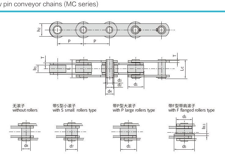
Some hollow pin conveyor-chain families are shown in rollerless, small-roller, large-roller and flanged-roller versions. Large rollers can reduce sliding on suitable rails, while flanged rollers can add lateral guidance. Rollerless or bush-running arrangements may suit compact or specially guided mechanisms. The rail material, speed, lubrication and contamination should be selected as a system.
When the replacement discussion also includes conventional roller-chain layouts, see the companion hollow pin roller chain resource for an additional product-focused reference. Use that external reference as a starting point only; the machine dimensions and duty conditions still govern the final chain selection.
4. Separate breaking load from working load
Catalogue tensile or breaking values are useful for comparing sizes and confirming product identity, but they are not a direct allowable working load. Real conveyor sizing must account for chain pull, acceleration, shock, starts per hour, vertical lift, friction, temperature, wear allowance and an appropriate engineering safety factor. For critical equipment, the machine designer should calculate the actual duty rather than selecting by a single tensile number.
5. Match the environment
Carbon-steel and stainless chain configurations behave differently in wet, abrasive, hot or chemically aggressive service. For washdown machinery, list the cleaning agent, concentration, temperature and rinse procedure. For dry food, powder or packaging lines, consider whether conventional lubrication is acceptable or whether contamination control changes the lubrication strategy. For outdoor or humid service, corrosion protection and storage conditions matter before the chain is even installed.
6. Confirm sprockets, tension and installation
Sprockets must match pitch and roller or bush geometry. Alignment errors force the chain against tooth flanks and guides, increasing wear. Install with the chain tension recommended for the conveyor architecture rather than pulling the chain tight. Conveyor chains need controlled slack so articulation can occur without excessive bearing pressure.
After commissioning, inspect the system under real load. Look for tight spots, uneven strand tension, roller skidding, guide rubbing, attachment contact and unusual noise. Recheck after the first production period because new components can bed in and fixtures may settle.
7. Build a maintenance record
Track chain elongation, roller or bush wear, plate damage, corrosion, stiff joints and attachment condition. When rods pass through hollow pins, include the rod-to-pin interface in the inspection. A maintenance record makes replacement decisions more objective and helps identify whether a change in product, cleaning cycle or conveyor speed is increasing wear.
RFQ checklist
- Model/family and exact pitch
- Hollow pin bore requirement
- Roller configuration
- Chain width and number of strands
- Attachment or cross-rod drawing
- Sprocket tooth count and center distance
- Speed, load, shock and starts per hour
- Temperature, corrosion and washdown exposure
- Quantity and destination
Use this checklist to compare catalogue candidates and then request an engineering confirmation before ordering. The goal is a chain-and-attachment system that fits the machine, carries the real duty and remains practical to maintain.
7. Build a cross-reference worksheet
A useful cross-reference worksheet puts the old chain and the proposed chain in adjacent columns. Include pitch, roller or bush diameter, width between inner plates, plate height, plate thickness, pin outside diameter, hollow-pin bore, overall pin length and the selected roller arrangement. Add sprocket tooth count, face width and shaft/bore information below the chain table. Differences become visible immediately and can be reviewed before a sample is ordered.
For twin-strand conveyors, add chain-center spacing and cross-rod length. If the attachment is offset from the chain centerline, record that lever arm because it changes the bending moment applied to the rod and plates. A dimension that appears minor on the chain drawing may become important when a long fixture is mounted to it.
8. Separate identification values from design loads
Historical catalogues often list tensile or breaking values. Those numbers are useful for identifying construction and comparing catalogue families, but they are not an allowable conveyor working load. A working design must consider speed, dynamic loading, shock, lubrication, number of engaged sprocket teeth, attachment forces and the machine builder’s design margin. Do not convert a breaking-load number directly into an operating load by applying an arbitrary factor.
9. Plan the maintenance task before finalizing the attachment
Ask how a technician will remove the cross-rod, how much axial clearance exists, whether a guard must be removed, and whether the rod can be withdrawn when adjacent products or machine frames are present. Good attachment geometry can shorten downtime more than a small increase in nominal chain size. Record the retention hardware and replacement part number in the machine documentation.
Frequently asked questions
What information should I send with an RFQ?
Include model if known, measured dimensions, sprocket details, attachment drawing, speed, load, environment and quantity.
Are catalogue tensile values working loads?
No. They are identification/comparison values. Allowable duty requires application engineering and current product confirmation.
Can an old chain be cross-referenced from a photo only?
A photo helps, but measurements and sprocket information are needed for a reliable dimensional cross-reference.